
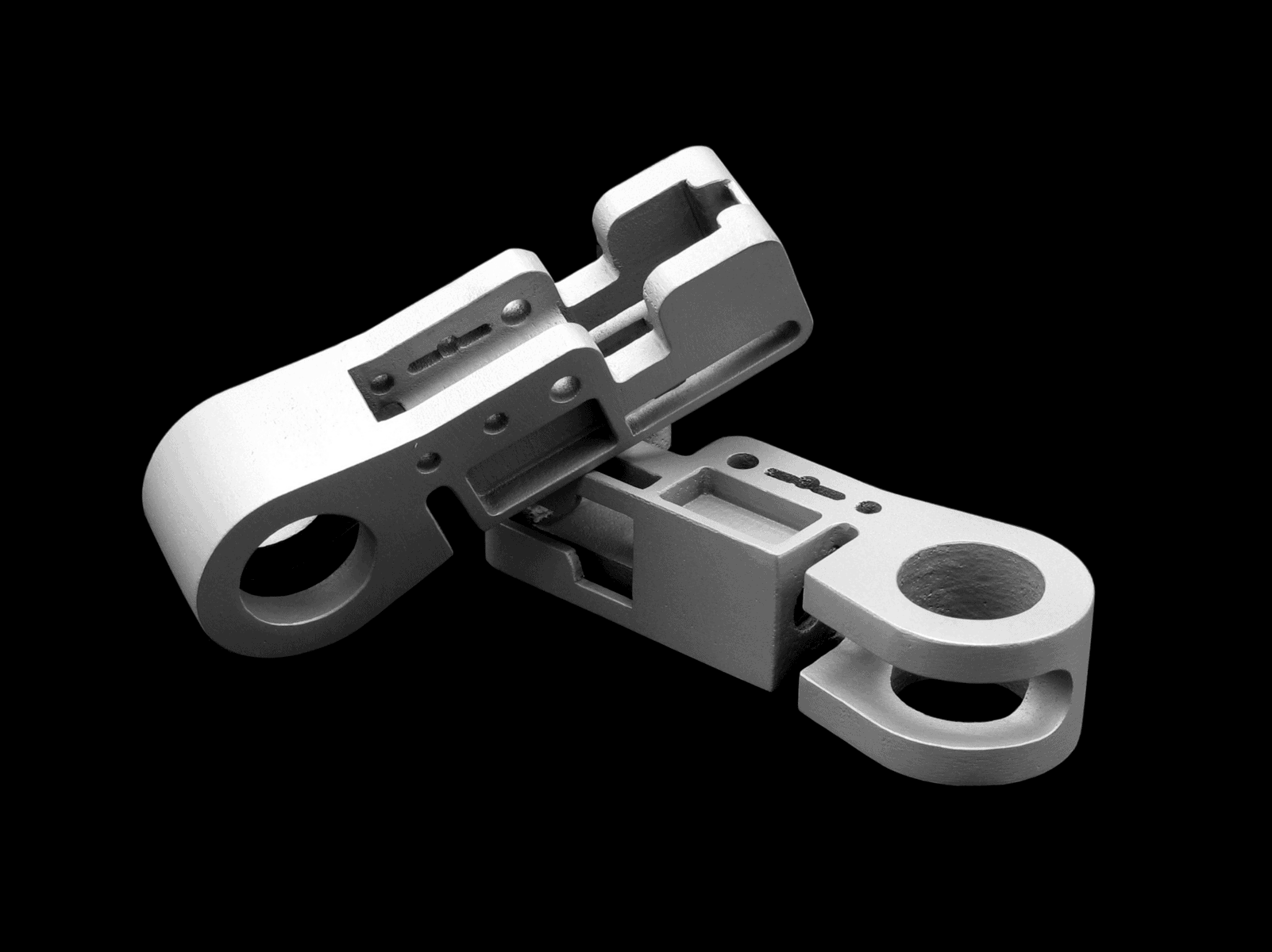
Direct Metal Laser Sintering, or laser sintering of metal in a powder bed in Swedish, offers manufacturing in many different metal alloys and is the most common technology for additive manufacturing of metal. Like the other processes for 3D printing in metal so DMLS produces materials such as 100% non-porous materials with material properties that are often better than the cast counterpart and material properties that resemble contagion. The process sinters and fuses metal powder with one or multiple lasers and is used on a large scale for the production of components that have high demands on material properties but where detail and surface finish are not the highest requirements. However, it must be said that DMLS still manufactures with very, very high accuracy and precision but we always recommend adding machining of those surfaces that require exact accuracy or for threaded holes. To achieve smooth and shiny surfaces, it is recommended to add polishing or plating. Additive manufacturing of metals is perfect when it comes to low-number, high-complexity components.
Are you unsure which process suits your purpose best? Then click here!
Characteristics
Colours
Characteristics
Colours
Characteristics
Colours
AlSi10Mg is a commonly used aluminum alloy in the casting industry that is used to manufacture components that require strength, hardness and light weight. Thanks to the high cooling rates during the printing process, the 3D printed aluminum becomes stronger than the cast counterpart. 3D printing of AlSi10Mg is widely used in the aerospace and automotive industries and the parts are easy to machine, polish, heat treat and surface treat just like any other traditionally manufactured aluminum part.
Technical specification
| Process data | Value |
|---|---|
| Standard tolerance | ± 0.2% (minimum limit ±0.2 mm) |
| Layer thickness | 0.03 – 0.1 mm |
| Minimum wall thickness | 0.8 mm |
| Minimal detail | 0.8 mm |
| Surface finish (blasted) | 60 ± 30 Rz |
| Largest component size | 500 x 280 x 315 mm |
Material properties
| Material data | Unit | Without finishing | Heat treated |
|---|---|---|---|
| Tensile strength | MPa | 420 ± 30 | 330 ± 25 |
| Elastic limit (Rp 0.2%) | MPa | 250 ± 30 | 225 ± 20 |
| Elongation at break | % | 5 ± 2 | 10 ± 3 |
| E-module | GPa | 65 ± 10 | 65 ± 10 |
| Hardness | HV10 | 120 ± 5 | 120 ± 5 |
| Density | g/cm³ | 2.7 | 2.7 |
| Component density | % | 99.5 | 99.5 |
| Thermal conductivity | W/m°C | – | 120 ± 10 |
| Specific heat capacity | J/(kg K) | 910 ± 50 | 910 ± 50 |
Values above are approximate and actual values may vary.
Technical specification
| Process data | Value |
|---|---|
| Standard tolerance | ± 0.3% (minimum limit ±0.3 mm) |
| Layer thickness | 0.03 – 0.1 mm |
| Minimum wall thickness | 0.8 mm |
| Minimal detail | 0.8 mm |
| Surface finish (blasted) | 60 ± 30 Rz |
| Largest component size | 500 x 280 x 315 mm |
Material properties
| Material data | Unit | Without finishing | Heat treated |
|---|---|---|---|
| Tensile strength | MPa | 420 ± 30 | 330 ± 25 |
| Elastic limit (Rp 0.2%) | MPa | 250 ± 30 | 225 ± 20 |
| Elongation at break | % | 5 ± 2 | 10 ± 3 |
| E-module | GPa | 65 ± 10 | 65 ± 10 |
| Hardness | HV10 | 120 ± 5 | 120 ± 5 |
| Density | g/cm³ | 2.7 | 2.7 |
| Component density | % | 99.5 | 99.5 |
| Thermal conductivity | W/m°C | – | 120 ± 10 |
| Specific heat capacity | J/(kg K) | 910 ± 50 | 910 ± 50 |
Values above are approximate and actual values may vary.
316L is a stainless steel and is a popular alloy for applications in mechanical engineering, the maritime and food industry and pharmaceutical purposes. Components made in 316L can be machined, polished, welded, heat treated and surface treated just like any other traditionally made stainless steel component.
Technical specification
| Process data | Value |
|---|---|
| Standard tolerance | ± 0.2% (minimum limit ±0.2 mm) |
| Layer thickness | 0.02 – 0.1 mm |
| Minimum permitted wall thickness | 0.8 mm |
| Minimal detail | 0.8 mm |
| Surface finish (blasted) | 60 ± 30 Rz |
| Largest component size | 270 x 270 x 345 mm |
Material properties
| Material data | Unit | Without finishing | Heat treated |
|---|---|---|---|
| Tensile strength | MPa | 600 ± 40 | 540 ± 50 |
| Elastic limit (Rp 0.2%) | MPa | 480 ± 40 | 370 ± 50 |
| Elongation at break | % | 40 ± 5 | 40 ± 10 |
| E-module | GPa | 170 ± 20 | 180 |
| Hardness | HRC | 16 ± 1 | 16 ± 1 |
| Density | g/cm³ | 7.9 | 7.9 |
| Component density | % | approx. 100 | approx. 100 |
| Thermal conductivity | W/m°C | – | – |
| Specific heat capacity | J/(kg K) | – | 500 |
Values above are approximate and actual values may vary.
Technical specification
| Process data | Value |
|---|---|
| Standard tolerance | ± 0.3% (minimum limit ±0.3 mm) |
| Layer thickness | 0.02 – 0.1 mm |
| Minimum permitted wall thickness | 0.8 mm |
| Minimal detail | 0.8 mm |
| Surface finish (blasted) | 60 ± 30 Rz |
| Largest component size | 270 x 270 x 345 mm |
Material properties
| Material data | Unit | Without finishing | Heat treated |
|---|---|---|---|
| Tensile strength | MPa | 600 ± 40 | 540 ± 50 |
| Elastic limit (Rp 0.2%) | MPa | 480 ± 40 | 370 ± 50 |
| Elongation at break | % | 40 ± 5 | 40 ± 10 |
| E-module | GPa | 170 ± 20 | 180 |
| Hardness | HRC | 16 ± 1 | 16 ± 1 |
| Density | g/cm³ | 7.9 | 7.9 |
| Component density | % | approx. 100 | approx. 100 |
| Thermal conductivity | W/m°C | – | – |
| Specific heat capacity | J/(kg K) | – | 500 |
Values above are approximate and actual values may vary.
17-4 PH is a stainless steel with high strength and good thermal properties. It is a material that is suitable for components that are exposed to high temperatures and loads and is therefore often used for components for engines and powertrains, among other things. Components made in 17-4 PH can be machined, polished, welded, heat treated and surface treated just like any other traditionally made stainless steel component.
Technical specification
| Process data | Value |
|---|---|
| Standard tolerance | ± 0.2% (minimum limit ±0.2 mm) |
| Layer thickness | 0.03 – 0.1 mm |
| Minimum permitted wall thickness | 0.8 mm |
| Minimal detail | 0.8 mm |
| Surface finish (blasted) | 60 ± 30 Rz |
| Largest component size | 500 x 280 x 315 mm |
Material properties
| Material data | Unit | Without finishing | Heat treated |
|---|---|---|---|
| Tensile strength | MPa | 1000 ± 90 | 1050 ± 50 |
| Elastic limit (Rp 0.2%) | MPa | 500 ± 90 | 430 ± 30 |
| Elongation at break | % | 22 ± 7 | 15 ± 2 |
| E-module | GPa | 170 ± 30 | 170 ± 30 |
| Hardness | HRC | 17 ± 2 | 17 ± 2 |
| Density | g/cm³ | – | – |
| Component density | % | – | – |
| Thermal conductivity | W/m°C | 14 ± 2 | 16 ± 3 |
| Specific heat capacity | J/(kg K) | 550 | 550 |
| Coefficient of thermal expansion | m/(m°C) | 14×10^-6 | 14×10^-6 |
Values above are approximate and actual values may vary.
Technical specification
| Process data | Value |
|---|---|
| Standard tolerance | ± 0.3% (minimum limit ±0.3 mm) |
| Layer thickness | 0.03 – 0.1 mm |
| Minimum permitted wall thickness | 0.8 mm |
| Minimal detail | 0.8 mm |
| Surface finish (blasted) | 60 ± 30 Rz |
| Largest component size | 500 x 280 x 315 mm |
Material properties
| Material data | Unit | Without finishing | Heat treated |
|---|---|---|---|
| Tensile strength | MPa | 930 ± 50 | 1230 ± 50 |
| Elastic limit (Rp 0.2%) | MPa | 510 ± 30 | 880 ± 30 |
| Elongation at break | % | 30 ± 4 | 21 ± 2 |
| E-module | GPa | 160 ± 15 | 157 ± 5 |
| Hardness | HRC | 17 ± 2 | 17 ± 2 |
| Density | g/cm³ | – | – |
| Component density | % | – | – |
| Thermal conductivity | W/m°C | 14 ± 2 | 16 ± 3 |
| Specific heat capacity | J/(kg K) | 550 | 550 |
| Coefficient of thermal expansion | m/(m°C) | 14×10^-6 | 14×10^-6 |
Values above are approximate and actual values may vary.
Inconel 718 is widely used in jet engines thanks to its very good mechanical properties even at very high working temperatures of over 600°C. This nickel-based superalloy can withstand very high stress and strain in extreme environments with large and rapid temperature changes. Iconel 718 is also highly resistant to corrosion, fatigue and creep.
Technical specification
| Process data | Value |
|---|---|
| Standard tolerance | ± 0.2% (minimum limit ±0.2 mm) |
| Layer thickness | 0.03 – 0.1 mm |
| Minimum wall thickness | 0.8 mm |
| Minimal detail | 0.8 mm |
| Surface finish (blasted) | 60 ± 30 Rz |
| Largest component size | 500 x 280 x 315 mm |
Material properties
| Material data | Unit | Value |
|---|---|---|
| Tensile strength | MPa | 930 ± 50 |
| Elastic limit (Rp 0.2%) | MPa | 650 ± 100 |
| Elongation at break | % | 26 ± 3 |
| E-module | GPa | 172 ± 16 |
| Hardness | HV10 | 293 ± 3 |
| Coefficient of thermal expansion | m/m°C | 16.6 – 17.2 x 10^6 |
| Maximum working temperature | °C | 650 |
Values above are approximate and actual values may vary.
Technical specification
| Process data | Value |
|---|---|
| Standard tolerance | ± 0.3% (minimum limit ±0.3 mm) |
| Layer thickness | 0.03 – 0.1 mm |
| Minimum wall thickness | 0.8 mm |
| Minimal detail | 0.8 mm |
| Surface finish (blasted) | 60 ± 30 Rz |
| Largest component size | 500 x 280 x 315 mm |
Material properties
| Material data | Unit | Value |
|---|---|---|
| Tensile strength | MPa | 930 ± 50 |
| Elastic limit (Rp 0.2%) | MPa | 650 ± 100 |
| Elongation at break | % | 26 ± 3 |
| E-module | GPa | 172 ± 16 |
| Hardness | HV10 | 293 ± 3 |
| Coefficient of thermal expansion | m/m°C | 16.6 – 17.2 x 10^6 |
| Maximum working temperature | °C | 650 |
Values above are approximate and actual values may vary.
Mar aging steel is a tool steel with very good mechanical properties and even better when heat treated. This steel is used for components subject to high wear and high loads such as gears, injection molding tools, components for factory lines and engine components. Components manufactured in mar-aged steel can be machined, polished, welded and heat treated.
Technical specification
| Process data | Value |
|---|---|
| Standard tolerance | ± 0.2% (minimum limit ±0.2 mm) |
| Layer thickness | 0.03 – 0.1 mm |
| Minimum permitted wall thickness | 0.8 mm |
| Minimal detail | 0.8 mm |
| Surface finish (blasted) | 50 ± 30 Rz |
| Largest component size | 500 x 280 x 315 mm |
Material properties
| Material data | Unit | Without finishing | Heat treated |
|---|---|---|---|
| Tensile strength | MPa | 1100 ± 100 | 1950 ± 100 |
| Elastic limit (Rp 0.2%) | MPa | 1000 ± 100 | 1900 ± 100 |
| Elongation at break | % | 9 ± 4 | 2 ± 1 |
| E-module | GPa | 170 ± 30 | 180 ± 20 |
| Hardness | HRC | 35 ± 2 | 52 ± 2 |
| Density | g/cm³ | – | – |
| Component density | % | – | – |
| Thermal conductivity | W/m°C | 15 ± 2 | 20 ± 2 |
| Specific heat capacity | J/(kg K) | 450 ± 20 | 450 ± 20 |
| Maximum operating temperature | °C | 400 | 400 |
Values above are approximate and actual values may vary.
Technical specification
| Process data | Value |
|---|---|
| Standard tolerance | ± 0.3% (minimum limit ±0.3 mm) |
| Layer thickness | 0.03 – 0.1 mm |
| Minimum permitted wall thickness | 0.8 mm |
| Minimal detail | 0.8 mm |
| Surface finish (blasted) | 50 ± 30 Rz |
| Largest component size | 500 x 280 x 315 mm |
Material properties
| Material data | Unit | Without finishing | Heat treated |
|---|---|---|---|
| Tensile strength | MPa | 1100 ± 100 | 1950 ± 100 |
| Elastic limit (Rp 0.2%) | MPa | 1000 ± 100 | 1900 ± 100 |
| Elongation at break | % | 9 ± 4 | 2 ± 1 |
| E-module | GPa | 170 ± 30 | 180 ± 20 |
| Hardness | HRC | 35 ± 2 | 52 ± 2 |
| Density | g/cm³ | – | – |
| Component density | % | – | – |
| Thermal conductivity | W/m°C | 15 ± 2 | 20 ± 2 |
| Specific heat capacity | J/(kg K) | 450 ± 20 | 450 ± 20 |
| Maximum operating temperature | °C | 400 | 400 |
Values above are approximate and actual values may vary.
Ti-6Al-4V is one of the most common titanium alloys. It has very good resistance to corrosion, very high strength for its low weight and is also biocompatible, which not only makes it optimal for racing, the aerospace industry, but also for prostheses and implants. Components made of titanium can be machined, polished and heat treated in the same way as traditionally made titanium components.
Technical specification
| Process data | Value |
|---|---|
| Standard tolerance | ± 0.5% (minimum limit ±0.2 mm) |
| Layer thickness | 0.03 – 0.1 mm |
| Minimum permitted wall thickness | 0.8 mm |
| Minimal detail | 0.8 mm |
| Surface finish (blasted) | 60 ± 40 Rz |
| Largest component size | 245 x 245 x 270 mm |
Material properties
| Material data | Unit | Without finishing | Heat treated |
|---|---|---|---|
| Tensile strength | MPa | 1200 ± 50 | 990 ± 30 |
| Elastic limit (Rp 0.2%) | MPa | 1060 ± 50 | 920 ± 30 |
| Elongation at break | % | 9 ± 4 | 14 ± 1 |
| E-module | GPa | 110 ± 10 | 115 ± 10 |
| Hardness | HV5 | 320 | 318 ± 10 |
| Density | g/cm³ | 4.41 | 4.41 |
| Component density | % | approx. 99.95 | approx. 99.95 |
| Thermal conductivity | W/m°C | – | – |
| Specific heat capacity | J/(kg K) | – | – |
| Maximum operating temperature | °C | 350 | 350 |
Values above are approximate and actual values may vary.
Technical specification
| Process data | Value |
|---|---|
| Standard tolerance | ± 0.5% (lowest limit ±0.3 mm) |
| Layer thickness | 0.03 – 0.1 mm |
| Minimum permitted wall thickness | 0.8 mm |
| Minimal detail | 0.8 mm |
| Surface finish (blasted) | 60 ± 40 Rz |
| Largest component size | 245 x 245 x 270 mm |
Material properties
| Material data | Unit | Without finishing | Heat treated |
|---|---|---|---|
| Tensile strength | MPa | 1200 ± 50 | 990 ± 30 |
| Elastic limit (Rp 0.2%) | MPa | 1060 ± 50 | 920 ± 30 |
| Elongation at break | % | 9 ± 4 | 14 ± 1 |
| E-module | GPa | 110 ± 10 | 115 ± 10 |
| Hardness | HV5 | 320 | 318 ± 10 |
| Density | g/cm³ | 4.41 | 4.41 |
| Component density | % | approx. 99.95 | approx. 99.95 |
| Thermal conductivity | W/m°C | – | – |
| Specific heat capacity | J/(kg K) | – | – |
| Maximum operating temperature | °C | 350 | 350 |
Values above are approximate and actual values may vary.
3D printing of copper opens completely new possibilities for energy efficiency of electricity and energy systems. Its high conductivity of heat and electricity means that it is widely used for applications with high demands on heat and current transmission. 3D printing of copper is predicted to have a very great importance for the energy transition and energy system of the future.
Technical specification
| Process data | Value |
|---|---|
| Standard tolerance | ± 0.2% (minimum limit ±0.2 mm) |
| Layer thickness | 0.03 – 0.1 mm |
| Minimum wall thickness | 0.8 mm |
| Minimal detail | 0.8 mm |
| Surface finish (blasted) | 60 ± 30 Rz |
| Largest component size | 500 x 280 x 315 mm |
Material properties
| Material data | Unit | Value |
|---|---|---|
| Tensile strength | MPa | 580 |
| Elastic limit (Rp 0.2%) | MPa | 500 |
| Elongation at break | % | 10 |
| Thermal conductivity | W/mK | 160 |
Values above are approximate and actual values may vary.
DMLS and SLM basically work in the same way and we have chosen to group both of these processes under the name DMLS. The process is as follows:
Almost all process parameters in SLM and DMLS are specified by the machine manufacturer. Depending on the size and geometry of the part and the properties of the metal powder, the layer height used in metal 3D printing varies from 20 to 50 microns.
A 3D printer for DMLS and SLM has a general print size of 250 x 150 x 150 mm, but larger machines are also available (up to 500 x 280 x 360 mm). The dimensional accuracy that DMLS can achieve is approximately 0.1 mm for form-stable geometries if the part does not settle.
Although SLM and DMLS printers can be used for small batch production, their capabilities are more comparable to those of FDM or SLA machines than SLS printers. Because the parts must be printed onto the build platform, they are limited by the XY print area available, which drags down their productivity.
SLM and DMLS use metal powder that is highly recyclable. Usually the waste is less than 5 %. The unused powder is collected, sieved and then mixed with new material to the level needed for the next print. Support structures, critical to the successful completion of fabrication, are really the only waste for 3D printing with DMLS and SLM.
DMLS and SLM produced parts have essentially isotropic mechanical and thermal properties. After heat treatment, they have almost negligible internal porosity, which is less than 0.2 % to 0.5 % in the printed state. Compared to components manufactured using conventional techniques, parts 3d printed with DMLS often have higher strength and hardness, although they are more sensitive to fatigue. For example, comparing the mechanical properties of A360 die cast alloy and 3d printed AlSi10Mg EOS metal alloy. These two materials share a similar chemical composition with significant silicon and magnesium content. Compared to die-cast objects, those created with 3D printing offer better mechanical properties and are harder.
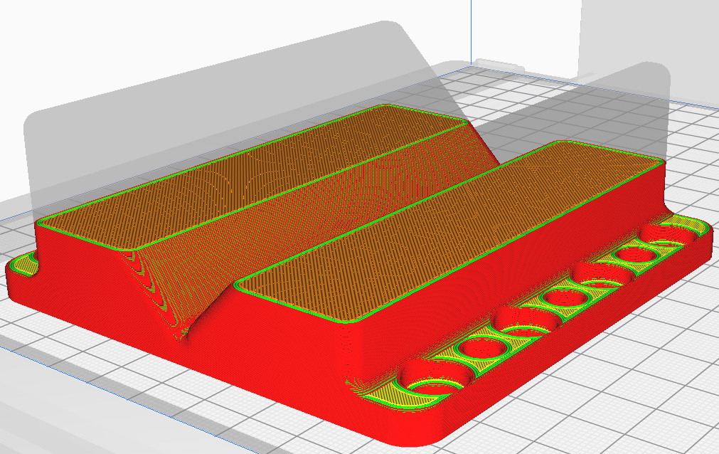
Due to the extremely high processing temperature, support structures are almost always necessary when 3d printing in metal. The support structures increase costs significantly by increasing the use of materials, taking longer to manufacture and requiring human post-processing.
Support structures have three functions when it comes to 3d printing in metal:
You should have support structure in mind when designing your detail, as this can sometimes be designed away from. Topology optimization methods are used to reduce the need for support structure and the risk of twisting as well as to improve mechanical performance and produce lightweight parts.
Large hollow parts are not commonly used in DMLS and SLM manufacturing because support structures cannot be easily removed, unlike polymer powder bed sintering techniques such as SLS and MJF. We recommend using diamond or teardrop cross-sections instead of circular for internal ducts larger than 8mm as they do not require any support structures.
Aluminum, stainless steel, titanium, cobalt chrome and Inconel are just a few of the metals and metal alloys that SLM and DMLS can use to create parts. The majority of industrial uses, from aircraft to medicine, are covered by these materials.
The mechanical properties, precision and aesthetics of the metal printed parts are improved by a variety of post-processing processes.
The removal of loose powder and support structures is a necessary post-processing step, and thermal annealing is often used to reduce residual stresses and improve the mechanical properties of the product.
Dimensionally decisive features can be CNC machined (such as holes or threads). A metal printed part's surface quality and fatigue strength can be increased by media blasting, metal plating, polishing and micromachining.
Because 3d printing in metal is relatively expensive, simulations are often used to predict how the object will behave when processed.

